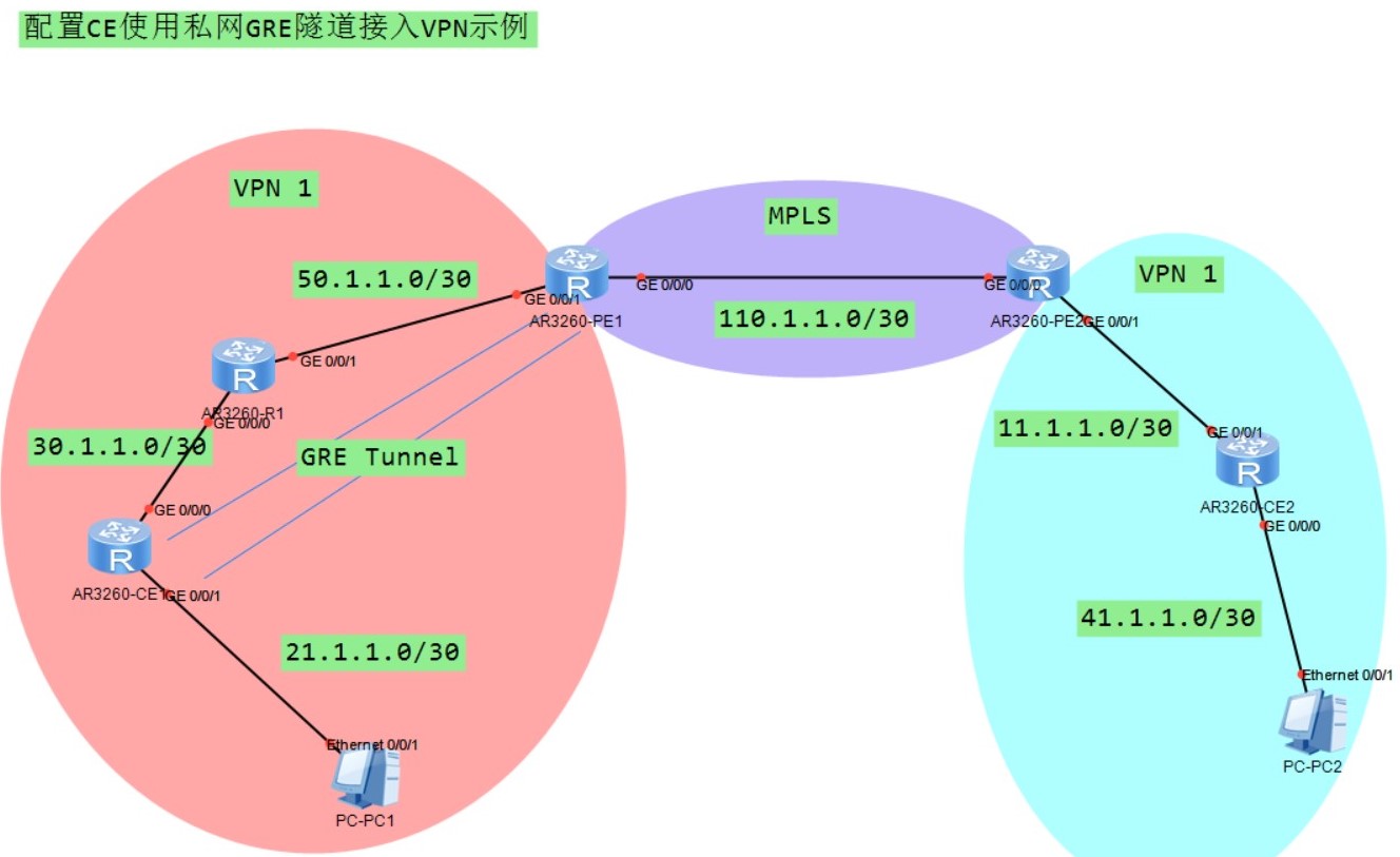
组网需求
- PE1与PE2组成MPLS骨干网
- CE1与PE1之间为私有网络,通过R1互联
- CE2与PE2直连
- CE2与CE1属于同一个VPN,要求他们之间互通
- PE1上没有与CE1的直连接口,无法将VPN实例与物理接口绑定
- 通过在CE1与PE1之间建立GRE隧道穿越私网,在PE1上将VPN与GRE隧道绑定,实现CE1通过GRE隧道接入到VPN中
组网拓扑
配置思路
- 在骨干网设备PE1与PE2上运行OSPF协议,实现互通,使能MPLS,OSPF进程为10
- 在CE1与PE1之间配置Tunnel接口,建立GRE隧道,使CE1与PE1直连
- 在PE1与PE2上建立VPN实例,并在PE1上将VPN实例与GRE隧道接口以及连接R1的物理接口进行绑定
- 在PE2上将VPN实例与连接CE2的物理接口绑定
- 在私网设备CE1、R1和PE1上运行OSPF协议实现互通,OSPF进程为20,PE1的OSPF 20绑定VP实例,使CE1通过GRE隧道接入VN
- 配置CE和PE间的路由,使用IS-IS路由协议
- 在PE之间配置BGP,完成CE1与CE2的互通
配置命令
配置各个路由器基本功能以及各个接口IP地址
PE1配置
1
2
3
4
5
6
7
8
sys
sys PE1
int g0/0/0
ip add 110.1.1.1 30
int g0/0/1
ip add 50.1.1.1 30
int LoopBack 0
ip add 1.1.1.9 32
PE2配置
1
2
3
4
5
6
7
8
sys
sys PE2
int g0/0/0
ip add 110.1.1.2 30
int g0/0/1
ip add 11.1.1.1 30
int LoopBack 0
ip add 3.3.3.9 32
CE1配置
1
2
3
4
5
6
sys
sys CE1
int g0/0/0
ip add 30.1.1.1 30
int g0/0/1
ip add 21.1.1.1 30
R1配置
1
2
3
4
5
6
sys
sys R1
int g0/0/1
ip add 50.1.1.2 30
int g0/0/0
ip add 30.1.1.2 30
CE2配置
1
2
3
4
5
6
sys
sys CE2
int g0/0/1
ip add 11.1.1.2 30
int g0/0/0
ip add 41.1.1.1 30
配置OSPF协议、MPLS,实现互通
PE1配置
1
2
3
4
5
6
7
8
9
10
11
12
13
14
sys
ospf 10
area 0
network 110.1.1.0 0.0.0.3
network 1.1.1.9 0.0.0.0
mpls lsr-id 1.1.1.9
mpls
lsp-trigger all
mpls ldp
quit
int g0/0/0
mpls
mpls ldp
PE2配置
1
2
3
4
5
6
7
8
9
10
11
12
13
14
15
sys
ospf 10
area 0
network 110.1.1.0 0.0.0.3
network 3.3.3.9 0.0.0.0
mpls lsr-id 3.3.3.9
mpls
lsp-trigger all
mpls ldp
quit
int g0/0/0
mpls
mpls ldp
配置VPN实例,并绑定接口
PE1配置
1
2
3
4
5
6
7
8
9
10
11
12
sys
ip vpn-instance vpn1
route-distinguisher 100:1
vpn-target 111:1 export-excommunity
vpn-target 111:1 import-excommunity
int g0/0/1
ip binding vpn-instance vpn1
ip add 50.1.1.1 30
int Tunnel 0/0/0
ip binding vpn-instance vpn1
ip add 2.2.2.2 30
PE2配置
1
2
3
4
5
6
7
8
9
sys
ip vpn-instance vpn1
route-distinguisher 200:1
vpn-target 111:1 export-excommunity
vpn-target 111:1 import-excommunity
int g0/0/1
ip binding vpn-instance vpn1
ip add 11.1.1.1 30
配置CE1侧的网络互通
PE1配置
1
2
3
4
sys
ospf 20 vpn-instance vpn1
area 0
network 50.1.1.0 0.0.0.3
R1配置
1
2
3
4
5
sys
ospf 20
area 0
network 50.1.1.0 0.0.0.3
network 30.1.1.0 0.0.0.3
CE1配置
1
2
3
4
sys
ospf 20
area 0
network 30.1.1.0 0.0.0.3
配置CE2侧的网络互通
PE2配置
1
2
3
4
5
6
7
sys
isis 50 vpn-instance vpn1
network-entity 50.0000.0000.0003.00
int g0/0/1
isis enable 50
isis small-hello
CE2配置
1
2
3
4
5
6
7
8
9
10
11
sys
isis 50
network 50.0000.0000.0004.00
int g0/0/1
isis enable 50
isis small-hello
int g0/0/0
isis enable 50
isis small-hello
配置CE1与PE1之间的隧道并通过IS-IS协议互通
PE1配置
1
2
3
4
5
6
7
8
9
10
11
12
13
sys
int Tunnel 0/0/0
ip add 2.2.2.2 30
tunnel-protocol gre
source 50.1.1.1
destination vpn-instance vpn1 30.1.1.1
isis 50 vpn-instance vpn1
network-entity 50.0000.0000.0001.00
int Tunnel 0/0/0
isis enable 50
isis small-hello
CE1配置
1
2
3
4
5
6
7
8
9
10
11
12
13
14
15
16
sys
int Tunnel 0/0/0
ip add 2.2.2.1 30
tunnel-protocol gre
source 30.1.1.1
destination 50.1.1.1
isis 50 vpn-instance vpn1
network-entity 50.0000.0000.0002.00
int Tunnel 0/0/0
isis enable 50
isis small-hello
int g0/0/1
isis enable 50
isis small-hello
配置BGP,在MPLS中运行MP-BGP
PE1配置
1
2
3
4
5
6
7
8
9
sys
bgp 100
peer 3.3.3.9 as-number 100
peer 3.3.3.9 connect-interface LoopBack 0
ipv4-family vpnv4
peer 3.3.3.9 enable
ipv4-family vpn-instance vpn1
import-route isis 50
PE2配置
1
2
3
4
5
6
7
8
9
sys
bgp 100
peer 1.1.1.9 as-number 100
peer 1.1.1.9 connect-interface LoopBack 0
ipv4-family vpnv4
peer 1.1.1.9 enable
ipv4-family vpn-instance vpn1
import-route isis 50
CE中引入PE的BGP路由
CE1配置
1
2
3
sys
isis 50
import-route bgp
CE2配置
1
2
3
sys
isis 50
import-route bgp
查看结果
查看到PC2的路由(在CE1上查看)
1
2
3
4
5
6
7
8
9
10
display ip routing-table 41.1.1.2
<CE1>dis ip routing-table 41.1.1.2
Route Flags: R - relay, D - download to fib
------------------------------------------------------------------------------
Routing Table : Public
Summary Count : 1
Destination/Mask Proto Pre Cost Flags NextHop Interface
41.1.1.0/30 ISIS-L2 15 74 D 2.2.2.2 Tunnel0/0/0